Estimate slab grid bars, footing runs, 20 ft stock count, weight, and lap splices for #3 through #11 rebar.
What this calculator returns
Two paths: a slab grid (length, width, on-center spacing) or a continuous footing/wall run (length × number of bars). Both modes return total linear feet, the count of 20 ft (or 10/40/60 ft) stock bars, total weight in pounds and kilograms, and an optional tie-wire estimate at one foot per intersection. Lap splices are added when a piece is longer than the chosen stock length.
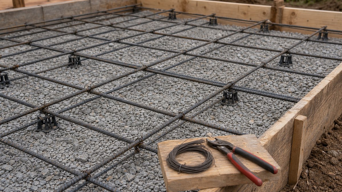
Worked example — 10×10 patio slab, #4 @ 12″ OC
- Cover: 3″ on each edge → usable length =
10 − 2×(3/12) = 9.5 ftin both directions. - Bars in each direction:
ceil(9.5×12 / 12) + 1 = ceil(9.5) + 1 = 11bars per direction. - Total linear feet:
11×9.5 + 11×9.5 = 209 ft. - 20 ft stock bars (no splice required, 9.5 < 20):
ceil(209 / 20) = 11bars. - Weight:
209 × 0.668 = 139.6 lb(≈63 kg) using ASTM A615 nominal weight for #4. - Tie wire at the 121 intersections: ≈121 ft (a 3.5 lb 17-gauge spool covers about 350 ft).
Bar reference — imperial #3–#11 and metric equivalents
| Imperial bar | Diameter (in) | Weight (lb/ft) | Metric equivalent | Diameter (mm) | Weight (kg/m) |
|---|---|---|---|---|---|
| #3 | 0.375 | 0.376 | 10M / 8 mm | 9.5 | 0.560 |
| #4 | 0.500 | 0.668 | 13M / 12 mm | 12.7 | 0.994 |
| #5 | 0.625 | 1.043 | 16M / 16 mm | 15.9 | 1.552 |
| #6 | 0.750 | 1.502 | 19M / 20 mm | 19.1 | 2.235 |
| #7 | 0.875 | 2.044 | 22M / 22 mm | 22.2 | 3.042 |
| #8 | 1.000 | 2.670 | 25M / 25 mm | 25.4 | 3.973 |
| #9 | 1.128 | 3.400 | 29M / 28 mm | 28.7 | 5.060 |
| #10 | 1.270 | 4.303 | 32M / 32 mm | 32.3 | 6.404 |
| #11 | 1.410 | 5.313 | 36M / 36 mm | 35.8 | 7.907 |
Source: CRSI Manual of Standard Practice (2018) and ASTM A615/A615M nominal dimensions. Metric ribbed bars per ISO 6935-2: 8/10/12/16/20/25 mm → 0.395/0.617/0.888/1.580/2.470/3.853 kg/m.
Common questions
How much concrete cover do I need?
For slab on grade with no soil contact below the steel, 2″ of cover top and bottom is the residential default; ACI 318 §20.5.1.3 calls for 3″ when concrete is cast against earth, which is why 3″ is preset for slab edges and footings here. Cover protects the bar from oxygen-and-chloride corrosion and is what makes the slab actually durable — under-covered rebar will rust, expand, and pop the concrete off in flakes within a decade.
Lap splice — 12·d or 40·d?
The two presets cover the practical extremes. 12·d (12× bar diameter) is a hand rule for compression splices in non-structural slabs — for #4, that is 6 inches. 40·d is a Class B tension splice approximation — for #4, 20 inches. The real number from ACI 318-19 §25.4 depends on f’c, bar coating, clear spacing, and confinement, and ranges roughly 30·d–60·d. For any structural footing, beam, or wall, use the lap schedule from your engineer’s drawings, not a rule of thumb.
Where do I splice the bars?
In a slab on grade you can splice anywhere — the bar grid is mat reinforcement, not flexural reinforcement. In a continuous footing or beam, splices belong at low-stress points: footings near the supports (top bars) or near midspan (bottom bars), and never all at the same cross-section. Stagger splices by at least the lap length so they do not overlap. Under no circumstances splice in a wall right at the base or at a window opening.
Once the steel is sized, the next step is the slab itself — see the concrete calculator for cubic yards, bag count, and ready-mix order. For continuous strip footings under walls, the concrete footing calculator handles trench volume and the perimeter math.
Material estimator only. Bar size, on-center spacing, lap length, hooks, ties, and cover for any load-bearing slab, footing, beam, wall, or column come from the project’s structural engineer working under ACI 318 (US), Eurocode 2 (EU), or the equivalent national code. Use this widget to size the trip to the rebar yard.
